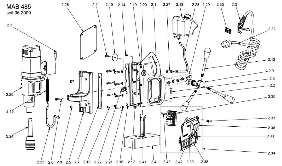
| П-п |
Арт |
Название |
| 2.1.1 |
 |
Housing for glued guide rails (both sides) until June 2009 |
| 2.1.2 |
 |
Housing for screwed guide rails (both sides) since June 2009 |
| 2.2 |
 |
Spring washer 6,1 DIN 7980 |
| 2.3 |
 |
Hexagon socket M6x20 DIN 912 |
| 2.4 |
 |
Magnet (electric) with indicator |
| 2.5 |
 |
Slide |
| 2.6 |
 |
Hexagon socket M6x35 DIN 912 |
| 2.7 |
 |
Rack |
| 2.8 |
 |
Hexagon socket M6x16 DIN 912 |
| 2.9 |
 |
Shaft for gear wheel |
| 2.10 |
 |
Washer for gear wheel 10,5x35x1,5 |
| 2.11 |
 |
Screw M6x16 ISO 7047 |
| 2.12 |
 |
Handle rod with knob |
| 2.13 |
 |
Coolant reservoir |
| 2.14 |
 |
Pressure piece |
| 2.15 |
 |
Spring for motor cable |
| 2.16.1 |
 |
Guide rail (1 set right/left) to be glued until June 2009 |
| 2.16.2 |
 |
Adjustment rail left, screwed, 4 holes since June 2009 |
| 2.17.1 |
 |
Guide rail right, screwed, 4 holes until June 2009 |
| 2.17.2 |
 |
Adjustment rail right, screwed, 4 holes since June 2009 |
| 2.18 |
 |
Hexagon socket M6x25 DIN 7984 |
| 2.19 |
 |
Nut M5 DIN 934 |
| 2.20 |
 |
Adjusting screw M5x16 DIN 913 |
| 2.21 |
 |
Washer 6,4x11x1,6 DIN 433 |
| 2.22 |
 |
Cable gland PG9 |
| 2.23 |
 |
Motor cable 670mm |
| 2.24 |
 |
Quick change drill chuck system Keyless CM2 |
| 2.25.1.1 |
 |
Motor complete 110V until March 2012 |
| 2.25.2.1 |
 |
Motor complete 110V since March 2012 |
| 2.25.1.2 |
 |
Motor complete 230V until March 2012 |
| 2.25.2.2 |
 |
Motor complete 230V since March 2012 |
| 2.26 |
 |
Cover of housing, back side |
| 2.27 |
 |
Quick change coupling |
| 2.28 |
 |
Coolant tube blue, short 260mm |
| 2.29 |
 |
Earthing complete |
| 2.30 |
 |
Cord grip for connection cable |
| 2.31 |
 |
Mains cable gland PG 11 |
| 2.32.1.1 |
 |
Connection cable 110 V with GB-plug |
| 2.32.2.1 |
 |
Connection cable 110V with US-plug |
| 2.32.1.2 |
 |
Connection cable 230V complete with plug |
| 2.33 |
 |
Screw M4x8 DIN 966 |
| 2.34.1 |
 |
Switch plate complete with PC board 3 relais 110V |
| 2.34.2 |
 |
Switch plate complete with PC board 3 relais 230V |
| 2.35.1 |
 |
Control board with 3 relais 110V |
| 2.35.2 |
 |
Control Board with 3 Relais 230 V |
| 2.36.1 |
 |
Actuator 110 V |
| 2.36.2 |
 |
Actuator 230V |
| 2.37 |
 |
Switch plate front side |
| 2.38 |
 |
Magnet switch, 4 connection terminals |
| 2.39 |
 |
LED display for indicator red/green incl. cable and frame |
| 2.40 |
 |
Fuse 2A, 5x20 |
| 2.41 |
 |
Indicator with cable |
| 2.42 |
 |
Rocker switch right/left |


